Product Description
SWC Series Cardan Shaft Universal Coupling With Flange Diameter 550mm For Rolling Mill
Brief Introduction
Why choose us!
Quality Control
Product Description
| structure | Type A | Flexible or Rigid | Rigid | Standard or Nonstandard | Standard |
| Materia | Alloy steel | Brand name | HangZhou XIHU (WEST LAKE) DIS. | Place of origin | ZheJiang ,China |
| Model | SWC550A | materials of yokes | 35CrMo | Length | customization |
| Flange DIA | 550mm | Nominal torque | 1000KN.m | coating | heavy duty industrial paint |
| Paint clour | customization | Application | Industrial machinery | OEM/ODM | Available |
| Certification | ISO,TUV,SGS | Price | calculate according to model | Custom service | Available |
Packaging & Delivery
Packaging details:Standard plywood case
Delivery detail: 15 -20 working days,depend on the actual produce condition
FAQ
Q: Are you trading company or manufacturer ?
A: We are a professional manufacturer specializing in manufacturing cardan shafts. We supply cardan shafts for the wholesalers , dealers and end-users from different countries.
Q: Can you do OEM? And what is your min order ?
A: Yes, absolutely. Generally, min order is1 set. Most of our products are Customized. Each order from our factory, we always produce cardan shaft after customer confirmed the drawing. So we didn’t have stock.
Q: How does your factory do regarding quality control?
A:Quality is priority! We always attach great importance to quality controlling from the very beginning to the end:
1) Firstly, we have QC department to control the quality
2) Secondly, we have all detailed records for nonconformity products, then we will make summary according to these records, avoid it happen again.
3) Thirdly,In order to meet world-class quality standards strict requirements, we passed the SGS, TUV product certification.
4)Fourthly,Have first-class production equipment, including CNC Machines and machining center.
/* January 22, 2571 19:08:37 */!function(){function s(e,r){var a,o={};try{e&&e.split(“,”).forEach(function(e,t){e&&(a=e.match(/(.*?):(.*)$/))&&1

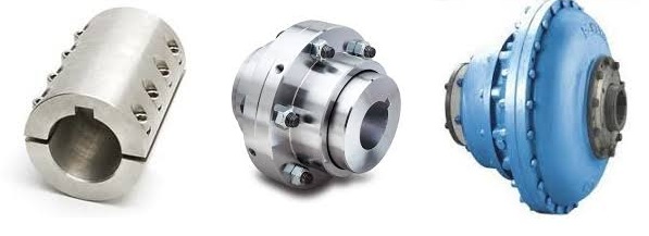
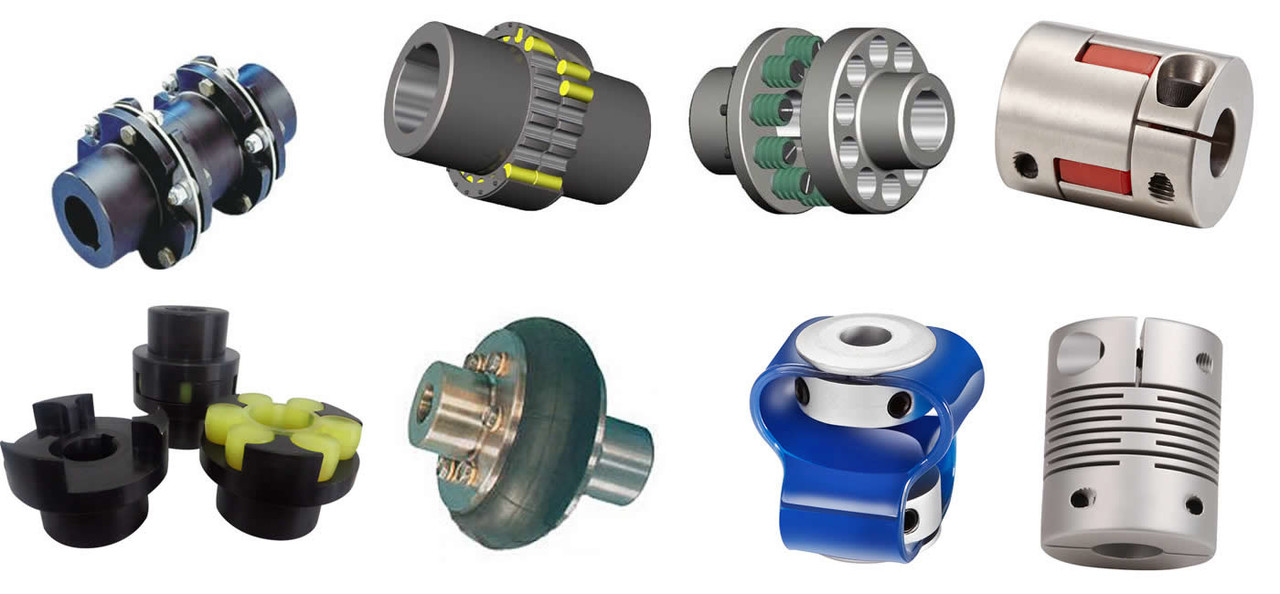
Can Shaft Couplings Compensate for Angular, Parallel, and Axial Misalignments?
Yes, shaft couplings are designed to compensate for different types of misalignments between rotating shafts in mechanical power transmission systems. They can handle the following types of misalignments:
- Angular Misalignment: This occurs when the shafts are not parallel and have an angle between them. Flexible couplings, such as elastomeric, beam, or Oldham couplings, can accommodate angular misalignments by allowing slight angular movement between the shafts while transmitting torque.
- Parallel Misalignment: This happens when the shafts are not collinear, resulting in axial displacement. Flexible couplings with lateral flexibility, like elastomeric or bellows couplings, can handle parallel misalignment by allowing limited lateral movement between the shafts.
- Radial Misalignment: Radial misalignment occurs when the shafts have lateral displacement but remain parallel. Flexible couplings, such as jaw or grid couplings, can absorb radial misalignment by permitting some lateral deflection while transmitting torque.
It is essential to note that while shaft couplings can compensate for misalignments to some extent, they do have their limits. The magnitude of misalignment they can handle depends on the type and design of the coupling. Exceeding the specified misalignment capabilities of a coupling can lead to premature wear, reduced efficiency, and possible coupling failure.
Therefore, when selecting a shaft coupling for an application, it is crucial to consider the expected misalignment and choose a coupling that can accommodate the anticipated misalignment range. Additionally, maintaining proper alignment through regular maintenance and periodic inspections is essential to ensure the coupling’s optimal performance and extend its service life.
“`
Temperature and Speed Limits for Different Shaft Coupling Types
The temperature and speed limits of shaft couplings vary depending on the materials and design of the coupling. Manufacturers provide specific guidelines and ratings for each coupling type. Below are general temperature and speed limits for some common shaft coupling types:
1. Elastomeric Couplings:
Elastomeric couplings, such as jaw couplings and tire couplings, typically have temperature limits ranging from -40°C to 100°C (-40°F to 212°F). The speed limits for elastomeric couplings are generally up to 5,000 RPM, but some designs may allow higher speeds.
2. Metallic Couplings:
Metallic couplings, like gear couplings and disc couplings, can handle a wider temperature range, typically from -50°C to 200°C (-58°F to 392°F). The speed limits for metallic couplings vary based on the size and design, but they can range from 3,000 RPM to over 10,000 RPM.
3. Grid Couplings:
Grid couplings have temperature limits similar to metallic couplings, ranging from -50°C to 200°C (-58°F to 392°F). The speed limits for grid couplings are typically in the range of 3,000 to 5,000 RPM.
4. Oldham Couplings:
Oldham couplings usually have temperature limits from -30°C to 100°C (-22°F to 212°F) and speed limits ranging from 1,000 to 5,000 RPM.
5. Beam Couplings:
Beam couplings generally have temperature limits from -40°C to 120°C (-40°F to 248°F) and speed limits between 5,000 to 10,000 RPM.
6. Fluid Couplings:
Fluid couplings are suitable for a wide range of temperatures, often from -50°C to 300°C (-58°F to 572°F). The speed limits depend on the size and design of the fluid coupling but can extend to several thousand RPM.
It’s important to note that these are general guidelines, and the actual temperature and speed limits may vary based on the specific coupling manufacturer, material quality, and application requirements. Always refer to the manufacturer’s documentation and technical specifications for accurate and up-to-date temperature and speed limits for a particular shaft coupling model.
“`
What is a Shaft Coupling and Its Role in Mechanical Power Transmission?
A shaft coupling is a mechanical device used to connect two shafts together at their ends, allowing for the transmission of mechanical power from one shaft to another. It serves as an essential component in various machinery and industrial applications where rotational motion needs to be transmitted between two shafts that are not perfectly aligned or are separated by a distance.
The role of a shaft coupling in mechanical power transmission includes the following:
1. Power Transmission:
The primary function of a shaft coupling is to transmit power from a driving shaft to a driven shaft. When the driving shaft rotates, the coupling transfers the rotational motion to the driven shaft, enabling the driven equipment to perform its intended function.
2. Misalignment Compensation:
In real-world applications, it is often challenging to achieve perfect alignment between two shafts due to manufacturing tolerances or dynamic conditions. Shaft couplings are designed to accommodate different types of misalignment, such as angular, parallel, and axial misalignment, allowing the equipment to function smoothly even when the shafts are not perfectly aligned.
3. Vibration Damping:
Shaft couplings can help dampen vibrations and shocks caused by uneven loads or sudden changes in the operating conditions. This vibration damping feature protects the connected components from damage and contributes to the overall system’s reliability.
4. Overload Protection:
In some cases, a shaft coupling can act as a safety device by providing overload protection. When the connected machinery experiences excessive torque or shock loads, certain types of couplings can disengage or shear to prevent damage to the equipment.
5. Torque and Speed Conversion:
Shaft couplings can be designed to provide torque and speed conversion between the driving and driven shafts. This allows for adaptation to different operating conditions and varying torque requirements in the connected machinery.
6. Flexible Connection:
Shaft couplings with flexible elements, such as elastomeric inserts or flexible discs, provide a flexible connection that can absorb shocks and misalignments. This flexibility helps reduce stress on the connected equipment and extends its lifespan.
Overall, shaft couplings are essential components in mechanical power transmission systems, enabling the efficient transfer of rotational motion between shafts while accommodating misalignments and providing protection against overloads and vibrations. The selection of the appropriate coupling type and design depends on the specific requirements of the application, including the type of misalignment, torque capacity, and operating conditions.
“`

editor by CX 2024-04-13
Leave a Reply