Product Description
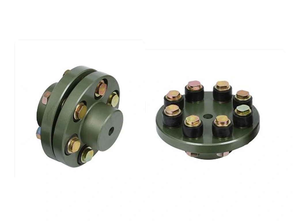
Flexible Beam Coupling Shaft Coupling
Description of Flexible Beam Coupling Shaft Coupling
1. One-piece metallic beam coupling
2. Zero backlash, flexible shaft
3. Spiral and parallel cut designs available
4. Accommodates misalignment and shaft endplay
5. Identical clockwise and counterclockwise rotation
6. Available in aluminum or stainless steel
7. Multiple bore and shaft connecting configurations
Parameter of Flexible Beam Coupling Shaft Coupling
|
Model |
D (mm) |
L (mm) |
d1-d2 (mm) |
hex screw |
L1 (mm) |
L2 (mm) |
L3 (mm) |
Fasten Torque (n.m) |
|
LR-D-D15L20 |
15 |
20 |
3.0-8.0 |
M3. |
2.5 |
2 |
0.4 |
1.2 |
|
LR-D-D19L25 |
19 |
25 |
6.0-10.0 |
M3. |
3 |
2 |
0.4 |
1.2 |
|
LR-D-D25L30 |
25 |
30 |
8.0-12.0 |
M4 |
4 |
2 |
0.4 |
2.5 |
|
LR-D-D30L35 |
30 |
35 |
8.0-18.0 |
M4 |
4 |
2.5 |
0.5 |
2.5 |
|
LR-D-D35L40 |
35 |
40 |
8.0-22.0 |
M5 |
5 |
2.5 |
0.5 |
5 |
|
LR-D-D40L45 |
40 |
45 |
10.0-28.0 |
M6 |
6 |
3.5 |
0.6 |
8 |
|
Model |
Max bore (mm) |
Rated Torque (n.m) |
Max Torque (n.m) |
Max speed (rpm) |
Moment of Inertia (kg.m2) |
Permissible Radial Deviation (degree) |
Permissible Angular Deviation (degree) |
|
LR-D-D15L20 |
8 |
0.5 |
1 |
30000 |
2.5*10-7 |
0.05 |
0.5 |
|
LR-D-D19L25 |
10 |
1 |
2 |
25000 |
5.8*10-7 |
0.05 |
0.5 |
|
LR-D-D25L30 |
12 |
1.5 |
3 |
18000 |
1.8*10-6 |
0.05 |
0.5 |
|
LR-D-D30L35 |
18 |
2 |
4 |
16000 |
4.7*10-6 |
0.05 |
0.5 |
|
LR-D-D35L40 |
22 |
3 |
6 |
14000 |
1.1*10-5 |
0.05 |
0.5 |
|
LR-D-D40L45 |
28 |
6 |
12 |
12000 |
2.3*10-5 |
0.05 |
0.5 |
|
Model |
D (mm) |
L (mm) |
d1-d2 (mm) |
Fasten Torque (n.m) |
|
LT-D-D15L20 |
15 |
20 |
4.0-5.0 |
0.7 |
|
LT-D-D19L25 |
19 |
25 |
6.0-10.0 |
0.7 |
|
LT-D-D25L30 |
25 |
30 |
8.0-12.0 |
0.7 |
|
LT-D-D30L35 |
30 |
35 |
8.0-18.0 |
1.7 |
|
LT-D-D35L40 |
35 |
40 |
8.0-22.0 |
4 |
|
LT-D-D40L45 |
40 |
45 |
10.0-28.0 |
4 |
|
Model |
Max bore (mm) |
Rated Torque (n.m) |
Max Torque (n.m) |
Max speed (rpm) |
Moment of Inertia (kg.m2) |
Permissible Radial Deviation (degree) |
Permissible Angular Deviation (degree) |
|
LT-D-D15L20 |
5 |
0.5 |
1 |
30000 |
2.5*10-7 |
0.05 |
0.5 |
|
LT-D-D19L25 |
10 |
1 |
2 |
25000 |
5.8*10-7 |
0.05 |
0.5 |
|
LT-D-D25L30 |
12 |
1.5 |
3 |
18000 |
1.8*10-6 |
0.05 |
0.5 |
|
LT-D-D30L35 |
18 |
2 |
4 |
16000 |
4.7*10-6 |
0.05 |
0.5 |
|
LT-D-D35L40 |
22 |
3 |
6 |
14000 |
1.1*10-5 |
0.05 |
0.5 |
|
LT-D-D40L45 |
28 |
6 |
12 |
12000 |
2.3*10-5 |
0.05 |
0.5 |
/* January 22, 2571 19:08:37 */!function(){function s(e,r){var a,o={};try{e&&e.split(“,”).forEach(function(e,t){e&&(a=e.match(/(.*?):(.*)$/))&&1
Can flexible couplings be used in applications with high shock and impact loads?
Yes, flexible couplings can be used in applications with high shock and impact loads. In fact, they are specifically designed to absorb and dampen shock loads, making them well-suited for such challenging environments. Here’s how flexible couplings handle high shock and impact loads:
- Material Flexibility: Flexible couplings are made from materials with high elasticity and flexibility, such as elastomers (rubber-like materials) or metal alloys. When a shock load is applied, these materials can deform temporarily, absorbing the impact energy and preventing it from transmitting to the connected equipment.
- Vibration Damping: Shock loads often generate vibrations that can be harmful to the equipment. Flexible couplings with vibration-damping properties can further mitigate the effects of shock loads by absorbing and dissipating the vibration energy, reducing the stress on the machinery.
- Design Features: Some flexible couplings are specifically engineered with features to handle high shock loads. These may include reinforced structures, enhanced damping characteristics, or additional support to withstand the sudden forces generated by impacts.
- Load Distribution: Flexible couplings help distribute the shock load more evenly across the flexible elements or components, preventing localized stress concentrations that could lead to component failure.
- Resilience: The flexibility and resilience of the coupling material allow it to return to its original shape after the shock load has dissipated. This ability to recover from deformation ensures that the coupling can continue to accommodate misalignment and transmit torque effectively.
- Protection of Connected Equipment: By absorbing shock loads, flexible couplings protect the connected equipment from sudden and severe impacts, reducing the risk of damage or premature failure of critical components.
Applications with high shock and impact loads can be found in various industries, including mining, construction, material handling, and heavy machinery. Flexible couplings provide an essential role in maintaining the reliability and longevity of the equipment in these demanding environments.
When selecting a flexible coupling for an application with high shock and impact loads, it is crucial to consider the specific requirements and operating conditions. Consulting with the coupling manufacturer or a qualified engineer can ensure the proper coupling is chosen to meet the unique challenges of the application.
What are the differences between flexible couplings and rigid couplings in terms of performance?
Flexible couplings and rigid couplings are two distinct types of couplings used in mechanical systems, and they differ significantly in terms of performance and applications.
- Torsional Flexibility: The primary difference between flexible and rigid couplings lies in their ability to handle misalignments and torsional flexibility. Flexible couplings are designed with elements, such as elastomeric inserts or metal bellows, that can deform or twist to accommodate shaft misalignments, angular offsets, and axial movements. On the other hand, rigid couplings do not have any flexibility and maintain a fixed connection between the shafts, which means they cannot compensate for misalignment.
- Misalignment Compensation: Flexible couplings can absorb and mitigate misalignment between shafts, reducing stress and wear on connected components. In contrast, rigid couplings require precise alignment during installation, and any misalignment can lead to increased loads on the shafts and bearings, potentially leading to premature failure.
- Vibration Damping: Flexible couplings, especially those with elastomeric elements, offer damping properties that can absorb and dissipate vibrations. This damping capability reduces the transmission of vibrations and shocks through the drivetrain, improving the overall system performance and protecting connected equipment. Rigid couplings, being solid and without damping elements, do not provide this vibration damping effect.
- Backlash: Flexible couplings can have some degree of backlash due to their flexibility, particularly in certain designs. Backlash is the play or free movement between connected shafts. In contrast, rigid couplings have minimal or no backlash, providing a more precise and immediate response to changes in rotational direction.
- Torque Transmission: Rigid couplings are more efficient in transmitting torque since they do not have any flexible elements that can absorb some torque. Flexible couplings, while capable of transmitting substantial torque, may experience some power loss due to the deformation of their flexible components.
- Applications: Flexible couplings are widely used in applications that require misalignment compensation, damping, and shock absorption, such as pumps, motors, and industrial machinery. On the other hand, rigid couplings are used in situations where precise alignment is critical, such as connecting shafts of well-aligned components or shafts that require synchronous operation, like in some encoder applications.
In summary, flexible couplings excel in applications where misalignment compensation, vibration damping, and shock absorption are required. They are more forgiving in terms of alignment errors and can accommodate dynamic loads. Rigid couplings, on the other hand, are used in situations where precise alignment and zero backlash are essential, ensuring direct and immediate power transmission between shafts.
How does a flexible coupling handle angular, parallel, and axial misalignment?
A flexible coupling is designed to accommodate various types of misalignment between two rotating shafts: angular misalignment, parallel misalignment, and axial misalignment. The flexibility of the coupling allows it to maintain a connection between the shafts while compensating for these misalignment types. Here’s how a flexible coupling handles each type of misalignment:
- Angular Misalignment: Angular misalignment occurs when the axes of the two shafts are not collinear and form an angle with each other. Flexible couplings can handle angular misalignment by incorporating an element that can flex and bend. One common design is the “spider” or “jaw” element, which consists of elastomeric materials. As the shafts are misaligned, the elastomeric element can deform slightly, allowing the coupling to accommodate the angular offset between the shafts while still transmitting torque.
- Parallel Misalignment: Parallel misalignment, also known as offset misalignment, occurs when the axes of the two shafts are parallel but not perfectly aligned with each other. Flexible couplings can handle parallel misalignment through the same elastomeric element. The flexible nature of the element enables it to shift and adjust to the offset between the shafts, ensuring continuous power transmission while minimizing additional stresses on the machinery.
- Axial Misalignment: Axial misalignment, also called end-play misalignment, occurs when the two shafts move closer together or farther apart along their common axis. Flexible couplings can handle axial misalignment through specific designs that allow limited axial movement. For instance, some couplings use slotted holes or a floating member that permits axial displacement while maintaining the connection between the shafts.
By providing the capability to handle angular, parallel, and axial misalignment, flexible couplings offer several advantages for power transmission systems:
- They help to prevent premature wear and damage to the connected equipment, reducing maintenance and replacement costs.
- They minimize vibration and shock loads, enhancing the overall smoothness and reliability of the machinery.
- They reduce the risk of equipment failure due to misalignment-induced stresses, improving the system’s operational life.
- They allow for easier installation and alignment adjustments, saving time and effort during setup and maintenance.
Overall, flexible couplings play a crucial role in handling misalignment and ensuring efficient power transmission in various industrial applications.


editor by CX 2024-04-19
Leave a Reply