Product Description
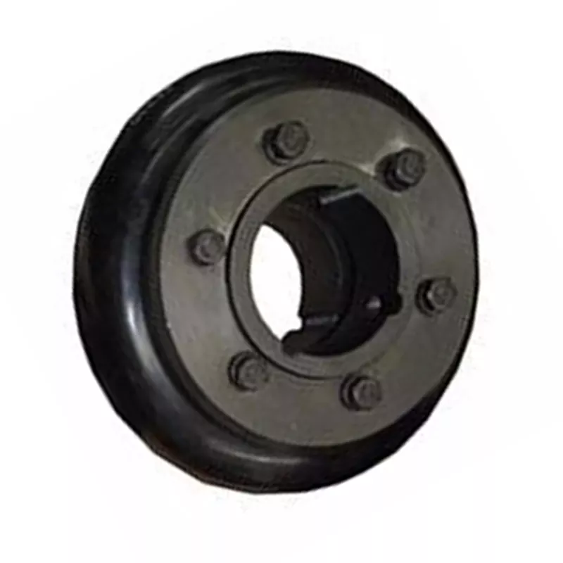
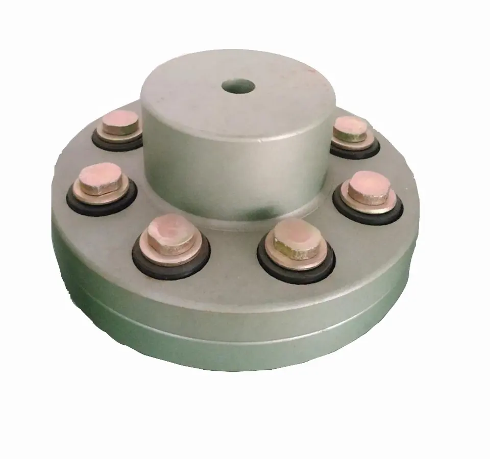
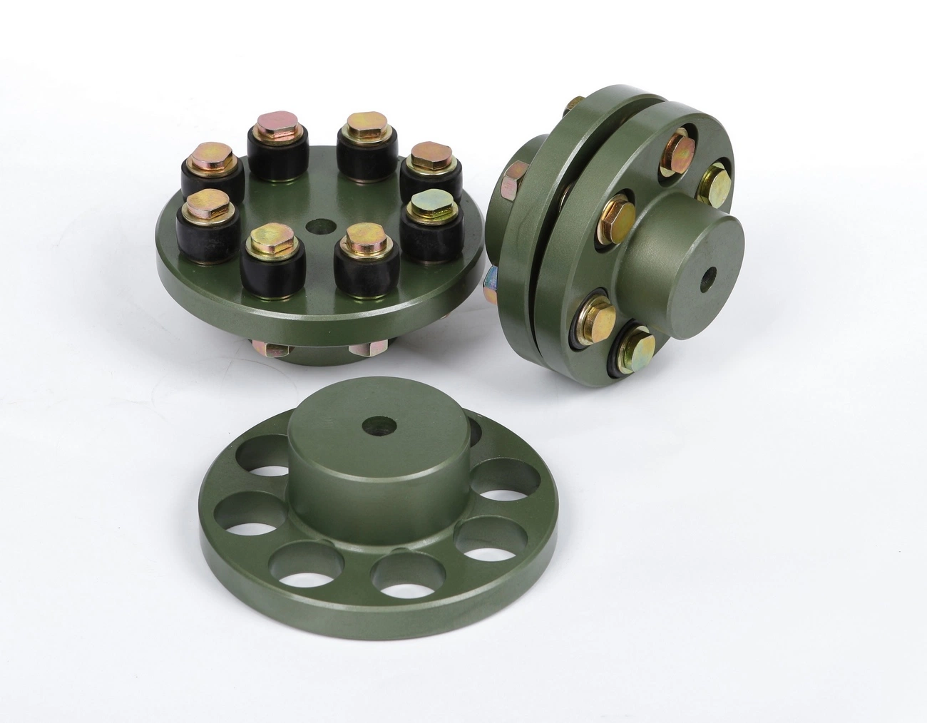
GFC Type Flexible Shaft Coupling GFC-25X30
GFC Type Flexible Shaft Coupling GFC-25X30
| model parameter | common bore diameter d1,d2 | ΦD | L | LF | LP | F | M | tightening screw torque (N.M) |
| GFC-14X22 | 3,4,5,6,6.35 | 14 | 22 | 14.3 | 6.6 | 5.0 | M2.5 | 1.0 |
| GFC-20×25 | 3,4,5,6,6.35,7,8,9,9.525,10 | 20 | 25 | 16.7 | 8.6 | 5.9 | M3 | 1.5 |
| GFC-20X30 | 3,4,5,6,6.35,7,8,9,9.525,10 | 20 | 30 | 19.25 | 8.6 | 5.9 | M3 | 1.5 |
| GFC-25X30 | 4,5,6,6.35,7,8,9,9.525,10,11,12 | 25 | 30 | 20.82 | 11.6 | 8.5 | M4 | 2.5 |
| GFC-25X34 | 4,5,6,6.35,7,8,9,9.525,10,11,12 | 25 | 34 | 22.82 | 11.6 | 8.5 | M4 | 2.5 |
| GFC-30×35 | 5,6,6.35,7,8,9,10,11,12,12.7,14,15,16 | 30 | 35 | 23 | 11.5 | 10 | M4 | 2.5 |
| GFC-30X40 | 5,6,6.35,7,8,9,10,11,12,12.7,14,15,16 | 30 | 40 | 25 | 11.5 | 10 | M4 | 2.5 |
| GFC-40X50 | 6,8,9,10,11,12,12.7,14,15,16,17,18,19,20,22,24 | 40 | 50 | 32.1 | 14.5 | 14 | M5 | 7 |
| GFC-40X55 | 6,8,9,10,11,12,12.7,14,15,16,17,18,19,20,22,24 | 40 | 55 | 34.5 | 14.5 | 14 | M5 | 7 |
| GFC-40X66 | 6,8,910,11,12,12.7,14,15,16,17,18,19,20,22,24 | 40 | 66 | 40 | 14.5 | 14 | M5 | 7 |
| GFC-55X49 | 10,11,12,12.7,14,15,16,17,18,19,20,22,24,25,28,30,32 | 55 | 49 | 32 | 16.1 | 13.5 | M6 | 12 |
| GFC-55X78 | 8,10,12,12.7,14,15,16,17,18,19,20,22,24,25,28,30,32 | 55 | 78 | 46.4 | 16.1 | 19 | M6 | 12 |
| GFC-65X80 | 14,15,16,17,18,19,20,22,24,25,28,30,32,35,38,40 | 65 | 80 | 48.5 | 17.3 | 14 | M8 | 20 |
| GFC-65X90 | 14,15,16,17,18,19,20,22,24,25,28,30,32,35,38,40 | 65 | 90 | 53.5 | 17.3 | 22.5 | M8 | 20 |
| GFC-80X114 | 19,20,22,24,25,28,30,32,35,38,40,42,45 | 80 | 114 | 68 | 22.5 | 16 | M8 | 20 |
| GFC-95X126 | 19,20,22,24,25,28,30,32,35,38,40,42,45,50,55 | 95 | 126 | 74.5 | 24 | 18 | M10 | 30 |
| model parameter | Rated torque (N.M)* |
allowable eccentricity (mm)* |
allowable deflection angle (°)* |
allowable axial deviation (mm)* |
maximum speed rpm |
static torsional stiffness (N.M/rad) |
moment of inertia (Kg.M2) |
Material of shaft sleeve | Material of shrapnel | surface treatment | weight (g) |
| GFC-14X22 | 5.0 | 0.1 | 1 | ±02 | 10000 | 50 | 1.0×10⁻⁶ | High strength aluminum alloy | Polyurethane imported from Germany | Anodizing treatment | 10 |
| GFC-20X25 | 5.0 | 0.1 | 1 | ±02 | 10000 | 50 | 1.0×10⁻⁶ | 15 | |||
| GFC-20X30 | 5.0 | 0.1 | 1 | ^02 | 10000 | 53 | 1.1×10⁻⁶ | 19 | |||
| GFC-25X30 | 10 | 0.1 | 1 | 10000 | 90 | 5.2X10⁻⁶ | 33 | ||||
| GFC-25X34 | 10 | 0.1 | 1 | £)2 | 10000 | 90 | 5.2×10⁻⁶ | 42 | |||
| GFC-30X35 | 12.5 | 0.1 | 1 | ±02 | 10000 | 123 | 6.2×10⁻⁶ | 50 | |||
| GFC-30×40 | 12.5 | 0.1 | 1 | 102 | 10000 | 123 | 6.2×10⁻⁶ | 60 | |||
| GFC-40X50 | 17 | 0.1 | 1 | 8000 | 1100 | 3.8×10⁻⁵ | 115 | ||||
| GFC-40X55 | 17 | 0.1 | 1 | ±02 | 8000 | 1100 | 3.8×10⁻⁵ | 127 | |||
| GFC-40X66 | 17 | 0.1 | 1 | 7000 | 1140 | 3.9×10⁻⁵ | 154 | ||||
| GFC-55X49 | 45 | 0.1 | 1 | ±02 | 6500 | 2350 | 1.6×10⁻³ | 241 | |||
| GFC-55X78 | 45 | 0.1 | 1 | 102 | 6000 | 2500 | 1.6×10⁻³ | 341 | |||
| GFC-65X80 | 108 | 0.1 | 1 | ±02 | 5500 | 4500 | 3.8×10⁻³ | 433 | |||
| GFC-65X90 | 108 | 0.1 | 1 | ±02 | 5500 | 4800 | 3.8×10⁻³ | 583 | |||
| GFC-80X114 | 145 | 0.1 | 1 | £)2 | 4500 | 5000 | 1.8×10⁻³ | 1650 | |||
| GFC-95X126 | 250 | 0.1 | 1 | ±02 | 4000 | 5000 | 2.0×10⁻³ | 1000 |
/* January 22, 2571 19:08:37 */!function(){function s(e,r){var a,o={};try{e&&e.split(“,”).forEach(function(e,t){e&&(a=e.match(/(.*?):(.*)$/))&&1
How do flexible couplings handle shaft misalignment in rotating equipment?
Flexible couplings are designed to handle shaft misalignment in rotating equipment, providing several key features that allow them to accommodate misalignment effectively. Here’s how they work:
- Angular Misalignment: Flexible couplings can handle angular misalignment, which occurs when the axes of the connected shafts are not perfectly aligned. The coupling’s flexible elements allow for slight angular deviation, ensuring that the torque can still be transmitted smoothly between the shafts.
- Parallel Misalignment: Parallel misalignment occurs when the connected shafts are not perfectly in line but run parallel to each other. Flexible couplings can compensate for this misalignment by utilizing their ability to flex or slide, allowing the shafts to remain connected while maintaining rotational integrity.
- Axial Misalignment: Axial misalignment refers to the situation where the connected shafts have a slight axial displacement. Some flexible couplings have specific designs to handle axial misalignment, allowing for limited movement along the axial direction without compromising the connection between the shafts.
- Double Flexing: Certain types of flexible couplings, such as the double-flexing couplings, can accommodate both angular and parallel misalignments simultaneously. These couplings use two sets of flexible elements to achieve this capability, providing a higher degree of misalignment compensation.
Overall, the flexibility of the coupling’s material and design allows it to bend, flex, or slide in response to the misalignment, reducing the stress on the connected equipment and ensuring smooth power transmission. By accommodating misalignment, flexible couplings help prevent premature wear, reduce vibration, and extend the service life of the rotating equipment.
How does a flexible coupling help in torque and rotational speed control?
A flexible coupling plays a crucial role in torque and rotational speed control in rotating machinery. It offers several benefits that contribute to efficient power transmission and help maintain desired operating conditions:
- Torque Transmission: Flexible couplings transmit torque from one shaft to another while accommodating misalignments. They provide a reliable connection that allows the driving shaft to transfer rotational force (torque) to the driven shaft without causing undue stress on the connected components.
- Smooth Power Transmission: Flexible couplings help reduce shocks and vibrations that can occur during startup, shutdown, or sudden load changes. By damping these vibrations, the coupling ensures smooth power transmission and protects the connected equipment from unnecessary wear.
- Rotational Speed Control: In certain applications, especially those involving precision motion control, maintaining consistent rotational speed is critical. Flexible couplings can help by minimizing backlash and torsional wind-up. Backlash refers to the play or gap between the coupling’s components, while torsional wind-up is the twisting deformation that can occur under torque load. Flexible couplings with low backlash and high torsional stiffness contribute to accurate rotational speed control.
- Compensation for Misalignment: Rotating machinery may experience misalignment due to various factors such as thermal expansion, foundation settling, or machining tolerances. Flexible couplings accommodate angular, parallel, and axial misalignments, which helps in maintaining proper alignment between the shafts and reduces unnecessary torque variations.
- Protection from Overloads: Flexible couplings can act as a mechanical fuse by disengaging or slipping when subjected to excessive torque loads. This feature protects the connected components from damage caused by sudden overloads or jamming events.
- Energy Efficiency: Certain types of flexible couplings, such as elastomeric couplings or beam couplings, have low mass and inertia. This characteristic reduces energy losses and contributes to overall system efficiency.
By providing reliable torque transmission, smooth power transfer, rotational speed control, and compensation for misalignment, flexible couplings optimize the performance and longevity of rotating machinery. Additionally, they enhance the safety and efficiency of various industrial processes by protecting equipment from excessive loads and ensuring smooth operation in diverse applications.
What are the differences between elastomeric and metallic flexible coupling designs?
Elastomeric and metallic flexible couplings are two distinct designs used to transmit torque and accommodate misalignment in mechanical systems. Each type offers unique characteristics and advantages, making them suitable for different applications.
Elastomeric Flexible Couplings:
Elastomeric flexible couplings, also known as flexible or jaw couplings, employ an elastomeric material (rubber or similar) as the flexible element. The elastomer is typically molded between two hubs, and it acts as the connector between the driving and driven shafts. The key differences and characteristics of elastomeric couplings include:
- Misalignment Compensation: Elastomeric couplings are designed to handle moderate levels of angular, parallel, and axial misalignment. The elastomeric material flexes to accommodate the misalignment while transmitting torque between the shafts.
- Vibration Damping: The elastomeric material in these couplings offers excellent vibration dampening properties, reducing the transmission of vibrations from one shaft to another. This feature helps protect connected equipment from excessive vibrations and enhances system reliability.
- Shock Load Absorption: Elastomeric couplings can absorb and dampen shock loads, protecting the system from sudden impacts or overloads.
- Cost-Effective: Elastomeric couplings are generally more cost-effective compared to metallic couplings, making them a popular choice for various industrial applications.
- Simple Design and Installation: Elastomeric couplings often have a straightforward design, allowing for easy installation and maintenance.
- Lower Torque Capacity: These couplings have a lower torque capacity compared to metallic couplings, making them suitable for applications with moderate torque requirements.
- Common Applications: Elastomeric couplings are commonly used in pumps, compressors, fans, conveyors, and other applications that require moderate torque transmission and misalignment compensation.
Metallic Flexible Couplings:
Metallic flexible couplings use metal components (such as steel, stainless steel, or aluminum) to connect the driving and driven shafts. The metallic designs can vary significantly depending on the type of metallic coupling, but some general characteristics include:
- High Torque Capacity: Metallic couplings have higher torque transmission capabilities compared to elastomeric couplings. They are well-suited for applications requiring high torque handling.
- Misalignment Compensation: Depending on the design, some metallic couplings can accommodate minimal misalignment, but they are generally not as flexible as elastomeric couplings in this regard.
- Stiffer Construction: Metallic couplings are generally stiffer than elastomeric couplings, offering less vibration dampening but higher torsional stiffness.
- Compact Design: Metallic couplings can have a more compact design, making them suitable for applications with limited space.
- Higher Precision: Metallic couplings often offer higher precision and concentricity, resulting in better shaft alignment.
- Higher Cost: Metallic couplings are typically more expensive than elastomeric couplings due to their construction and higher torque capacity.
- Common Applications: Metallic couplings are commonly used in high-speed machinery, precision equipment, robotics, and applications with high torque requirements.
Summary:
In summary, the main differences between elastomeric and metallic flexible coupling designs lie in their flexibility, torque capacity, vibration dampening, cost, and applications. Elastomeric couplings are suitable for applications with moderate torque, misalignment compensation, and vibration dampening requirements. On the other hand, metallic couplings are chosen for applications with higher torque and precision requirements, where flexibility and vibration dampening are less critical.


editor by CX 2024-04-25
Leave a Reply