Product Description
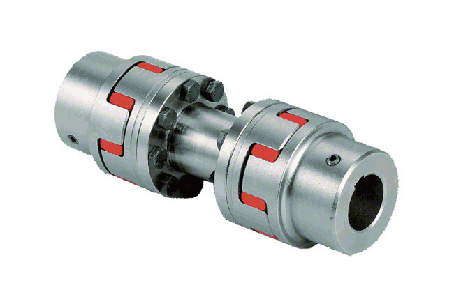
GIC-38x41Aluminum Alloy Parallel Line Clamping Rigid Shaft Coupling
Description of GIC-38x41Aluminum Alloy Parallel Line Clamping Rigid Shaft Coupling
>Integrated structure, the overall use of high-strength aluminum alloy materials
>Elastic action compensates radial, angular and axial deviation
>No gap shaft and sleeve connection, suitable for CHINAMFG and reverse rotation
>Designed for encoder and stepper motor
>Fastening method of clamping screw
Catalogue of GIC-38x41Aluminum Alloy Parallel Line Clamping Rigid Shaft Coupling
|
model parameter |
common bore diameter d1,d2 |
ΦD |
L |
L1 |
L2 |
F |
M |
tightening screw torque |
|
GIC-12xl8.5 |
2,3,4,5,6 |
12 |
18.5 |
0.55 |
1.3 |
2.5 |
M2.5 |
1 |
|
GIC-16xl6 |
3,4,5,6,6.35 |
16 |
16 |
0.55 |
1.4 |
3.18 |
M2.5 |
1 |
|
GIC-16×23 |
3,4,5,6,6.35 |
16 |
23 |
0.55 |
1.4 |
3.18 |
M2.5 |
1 |
|
GIC-19×23 |
3,4,5,6,6.35,7,8 |
19 |
23 |
0.55 |
1.4 |
3.18 |
M2.5 |
1 |
|
GIC-20×20 |
4,5,6,6.35,7,8,10 |
20 |
20 |
0.55 |
1.5 |
3.75 |
M2.5 |
1 |
|
GIC-20×26 |
4,5,6,6.35,7,8,10 |
20 |
26 |
0.55 |
1.5 |
3.75 |
M3 |
1.5 |
|
GIC-25×25 |
5,6,6.35,7,8,9,9.525,10,11,12 |
25 |
25 |
0.6 |
1.7 |
4.84 |
M3 |
1.5 |
|
GIC-25×31 |
5,6,6.35,7,8,9,9.525,10,11,12 |
25 |
31 |
0.6 |
1.8 |
4.46 |
M3 |
1.5 |
|
GIC-28.5×38 |
6,6.35,8,9,9.525,10,11,12,12.7,14 |
28.5 |
38 |
0.8 |
2.1 |
5.62 |
M4 |
2.5 |
|
GIC-32×32 |
8,9,9.525,10,11,12,12.7,14,15,16 |
32 |
32 |
0.8 |
2.3 |
6.07 |
M4 |
2.5 |
|
GIC-32×41 |
8,9,9.525,10,11,12,12.7,14,15,16 |
32 |
41 |
0.8 |
2.3 |
6.02 |
M4 |
2.5 |
|
GIC-38×41 |
8,9,9.525,10,11,12,14,15,16,17,18,19 |
38 |
41 |
0.8 |
2.7 |
5.32 |
M5 |
7 |
|
GIC-40×50 |
8,9,9.525,10,11,12,14,15,16,17,18,19,20 |
40 |
50 |
0.8 |
2.7 |
6.2 |
M5 |
7 |
|
GIC-40×56 |
8,10,11,12,12.7,14,15,16,17,18,19,20 |
40 |
56 |
0.8 |
2.7 |
8.5 |
M5 |
7 |
|
GIC-42×50 |
10,11,12,12.7,14,15,16,17,18,19,20,22,24 |
42 |
50 |
0.8 |
2.7 |
6.2 |
M5 |
7 |
|
GIC-50×50 |
10,12,12.7,14,15,16,17,18,19,20,22,24,25,28 |
50 |
50 |
0.8 |
2.9 |
7.22 |
M6 |
12 |
|
GIC-50×71 |
10,12,12.7,14,15,16,17,18,19,20,222425,28 |
50 |
71 |
0.8 |
3.3 |
8.5 |
M6 |
12 |
|
model parameter |
Rated torque(N.m) |
allowable eccentricity (mm) |
allowable deflection angle (°) |
allowable axial deviation (mm) |
maximum speed (rpm) |
static torsional stiffness (N.M/rad) |
weight (g) |
|
GIC-12xl8.5 |
0.5 |
0.1 |
2 |
±0.2 |
11000 |
60 |
4.8 |
|
GIC-16xl6 |
0.5 |
0.1 |
2 |
±0.2 |
10000 |
80 |
8 |
|
GIC-16×23 |
0.5 |
0.1 |
2 |
±0.2 |
9500 |
80 |
9.3 |
|
GIC-19×23 |
1 |
0.1 |
2 |
±0.2 |
9500 |
80 |
13 |
|
GIC-20×20 |
1 |
0.1 |
2 |
±0.2 |
10000 |
170 |
14 |
|
GIC-20×26 |
1 |
0.1 |
2 |
±0.2 |
7600 |
170 |
16.5 |
|
GIC-25×25 |
2 |
0.15 |
2 |
±0.2 |
6100 |
780 |
26 |
|
GIC-25×31 |
2 |
0.15 |
2 |
±0.2 |
6100 |
380 |
29 |
|
GIC-28.5×38 |
3 |
0.15 |
2 |
±0.2 |
5500 |
400 |
51 |
|
GIC-32×32 |
4 |
0.15 |
2 |
±0.2 |
5000 |
1100 |
56 |
|
GIC-32×41 |
4 |
0.15 |
2 |
±0.2 |
500 |
500 |
65 |
|
GIC-38×41 |
6.5 |
0.2 |
2 |
±0.2 |
650 |
650 |
107 |
|
GIC-40×50 |
6.5 |
0.2 |
2 |
±0.2 |
600 |
650 |
135 |
|
GIC-40×56 |
8 |
0.2 |
2 |
±0.2 |
800 |
800 |
142 |
|
GIC-42×50 |
8.5 |
0.2 |
2 |
±0.2 |
800 |
850 |
135 |
|
GIC-50×50 |
20 |
0.2 |
2 |
±0.2 |
1000 |
1000 |
220 |
|
GIC-50×71 |
20 |
0.2 |
2 |
±0.2 |
1000 |
1000 |
330 |
/* January 22, 2571 19:08:37 */!function(){function s(e,r){var a,o={};try{e&&e.split(“,”).forEach(function(e,t){e&&(a=e.match(/(.*?):(.*)$/))&&1

Is It Possible to Replace a Shaft Coupling Without Professional Assistance?
Yes, it is possible to replace a shaft coupling without professional assistance, especially if you have some mechanical knowledge and the necessary tools. However, the ease of replacement can vary depending on the type of coupling and the complexity of the equipment. Here are some general steps to guide you through the process:
1. Safety First:
Before starting any work, ensure that the equipment is turned off and disconnected from the power source. Use appropriate personal protective equipment (PPE) to protect yourself from potential hazards.
2. Assess the Coupling Type:
Different types of couplings may have specific installation and removal methods. Identify the type of coupling you need to replace, and consult the manufacturer’s documentation or online resources for guidance.
3. Gather Tools and Materials:
Collect the necessary tools, such as wrenches, sockets, and a puller (if required), to safely remove the old coupling. Have the new coupling ready for installation, ensuring it matches the specifications of the old one.
4. Disassembly:
If your coupling is a split or clamp-style coupling, you may be able to replace it without fully disassembling the connected equipment. Otherwise, you may need to remove other components to access the coupling.
5. Remove Fasteners:
Loosen and remove any fasteners, such as set screws, that secure the old coupling to the shafts. Take care not to damage the shafts during this process.
6. Extraction:
If the old coupling is tightly fitted on the shafts, you may need to use a coupling puller or other appropriate extraction tools to safely remove it.
7. Clean and Inspect:
After removing the old coupling, clean the shaft ends and inspect them for any signs of damage or wear. Also, check for any misalignment issues that may have contributed to the old coupling’s failure.
8. Install New Coupling:
Follow the manufacturer’s instructions for installing the new coupling. Apply appropriate lubrication and ensure the coupling is correctly aligned with the shafts.
9. Fasten Securely:
Tighten the fasteners to the manufacturer’s recommended torque values to securely attach the new coupling to the shafts.
10. Test Run:
After installation, perform a test run of the equipment to ensure the new coupling operates smoothly and without issues.
While it is possible to replace a shaft coupling without professional assistance, keep in mind that some couplings and equipment may require specialized knowledge and tools for safe and proper replacement. If you are uncertain about the process or encounter any difficulties, it is advisable to seek help from a qualified professional or technician to avoid potential damage to the equipment or injury to yourself.
“`
Can Shaft Couplings Handle Reversing Loads and Shock Loads Effectively?
Yes, shaft couplings are designed to handle both reversing loads and shock loads effectively, but the capability depends on the specific type of coupling and its design.
Reversing Loads:
Many shaft couplings, such as elastomeric couplings, gear couplings, and grid couplings, can handle reversing loads without any issue. Reversing loads occur when the direction of the torque changes periodically, causing the shafts to rotate in opposite directions. The flexibility of elastomeric couplings and the sturdy design of gear and grid couplings allow them to accommodate these reversing loads while maintaining reliable torque transmission.
Shock Loads:
Shock loads are sudden and high-magnitude forces that occur during start-up, sudden stops, or impact events. Shaft couplings with shock-absorbing features, such as elastomeric couplings and grid couplings, excel at handling shock loads. The elastomeric material in elastomeric couplings and the grid element in grid couplings act as shock absorbers, reducing the impact on the connected equipment and minimizing the risk of damage to the coupling itself.
It’s essential to select the appropriate coupling type based on the specific application’s requirements, including the magnitude and frequency of reversing loads and shock loads. Some couplings may have limitations on the amount of shock load they can handle, so it’s crucial to refer to the manufacturer’s specifications and guidelines for proper coupling selection.
In heavy-duty applications with high reversing loads and shock loads, it may be necessary to consider specialized couplings designed explicitly for such conditions, like disc couplings or fluid couplings, which can offer even better performance in handling these challenging load conditions.
“`
What is a Shaft Coupling and Its Role in Mechanical Power Transmission?
A shaft coupling is a mechanical device used to connect two shafts together at their ends, allowing for the transmission of mechanical power from one shaft to another. It serves as an essential component in various machinery and industrial applications where rotational motion needs to be transmitted between two shafts that are not perfectly aligned or are separated by a distance.
The role of a shaft coupling in mechanical power transmission includes the following:
1. Power Transmission:
The primary function of a shaft coupling is to transmit power from a driving shaft to a driven shaft. When the driving shaft rotates, the coupling transfers the rotational motion to the driven shaft, enabling the driven equipment to perform its intended function.
2. Misalignment Compensation:
In real-world applications, it is often challenging to achieve perfect alignment between two shafts due to manufacturing tolerances or dynamic conditions. Shaft couplings are designed to accommodate different types of misalignment, such as angular, parallel, and axial misalignment, allowing the equipment to function smoothly even when the shafts are not perfectly aligned.
3. Vibration Damping:
Shaft couplings can help dampen vibrations and shocks caused by uneven loads or sudden changes in the operating conditions. This vibration damping feature protects the connected components from damage and contributes to the overall system’s reliability.
4. Overload Protection:
In some cases, a shaft coupling can act as a safety device by providing overload protection. When the connected machinery experiences excessive torque or shock loads, certain types of couplings can disengage or shear to prevent damage to the equipment.
5. Torque and Speed Conversion:
Shaft couplings can be designed to provide torque and speed conversion between the driving and driven shafts. This allows for adaptation to different operating conditions and varying torque requirements in the connected machinery.
6. Flexible Connection:
Shaft couplings with flexible elements, such as elastomeric inserts or flexible discs, provide a flexible connection that can absorb shocks and misalignments. This flexibility helps reduce stress on the connected equipment and extends its lifespan.
Overall, shaft couplings are essential components in mechanical power transmission systems, enabling the efficient transfer of rotational motion between shafts while accommodating misalignments and providing protection against overloads and vibrations. The selection of the appropriate coupling type and design depends on the specific requirements of the application, including the type of misalignment, torque capacity, and operating conditions.
“`

editor by CX 2024-04-25
by
Leave a Reply