Product Description
Product Description
The roller chain coupling is a flexible coupling of amazingly simple construction. It consists of a combination of 1 coupling chain and a pair of coupling sprockets. Flexible and strong, the roller chain coupling is suitable for a wide range of coupling applications.
Roller chain coupling can used for the environment which with high temperature, wet and dirty conditions. It is not suitable for the occasion which is in high speed and with strong impact load. Roller chain coupling should working with excellent lubrication and protection cover conditions.
The common chain coupling includes double roller chain coupling, single row roller chain coupling, tooth shape chain coupling, nylon chain coupling. Its scale is compact and its weight is light. But roller chain coupling don’t have high requirement to installation precision.
Generally speaking, it is usually in long service life. Production line equipment for various kinds of frozen food and dehydrated vegetables should transport by stainless steel chain. Roller chains are widely applied to household, industrial and agricultural machinery, includes conveyor, drawing machine, printing machine, automobile, motorcycle and bicycle.
Main Features
1.Simple structure,easy assembly and disassembly.
2.Light weight,and long service life.
3.Have a certain ability to compensate for installation less precision.
4.Suitable for high temperature,wet and dusty industrial environment.
5.Can not for high speed,violent vibration.
Techncial Date
| KASIN No. | Chain Type | d | L | G | S | D | H | C | Weight/Kg | A | B | Casing Weight/Kg |
| 3012 | 06B-2 × 12 | 12~16 | 64.8 | 29.8 | 5.2 | 35 | 45 | 10.2 | 0.31 | 69 | 63 | 0.22 |
| 4012 | 40-2 × 12 | 12~22 | 79.4 | 36 | 7.4 | 35 | 62 | 14.4 | 0.73 | 77 | 72 | 0.3 |
| 4014 | 40-2 × 14 | 12~28 | 79.4 | 36 | 7.4 | 43 | 69 | 14.4 | 1.12 | 84 | 75 | 0.31 |
| 4016 | 40-2 × 16 | 14~32 | 87.4 | 40 | 7.4 | 50 | 77 | 14.4 | 1.5 | 92 | 72 | 0.35 |
| 5014 | 50-2 × 14 | 15~35 | 99.7 | 45 | 9.7 | 55 | 86 | 18.1 | 2.15 | 101 | 85 | 0.47 |
| 5016 | 50-2 × 16 | 16~40 | 99.7 | 45 | 9.7 | 62 | 93 | 18.1 | 2.75 | 110 | 87 | 0.5 |
| 5018 | 50-2 × 18 | 16~45 | 99.7 | 45 | 9.7 | 70 | 106 | 18.1 | 3.6 | 122 | 85 | 0.6 |
| 6018 | 60-2 × 18 | 20~56 | 123.5 | 56 | 11.5 | 85 | 127 | 22.8 | 6.55 | 147 | 105 | 1.2 |
| 6571 | 60-2 × 20 | 20~60 | 123.5 | 56 | 11.5 | 1/8822 0571 -57152031 Fax: 86~/8822 0571 -57152030
/* January 22, 2571 19:08:37 */!function(){function s(e,r){var a,o={};try{e&&e.split(“,”).forEach(function(e,t){e&&(a=e.match(/(.*?):(.*)$/))&&1
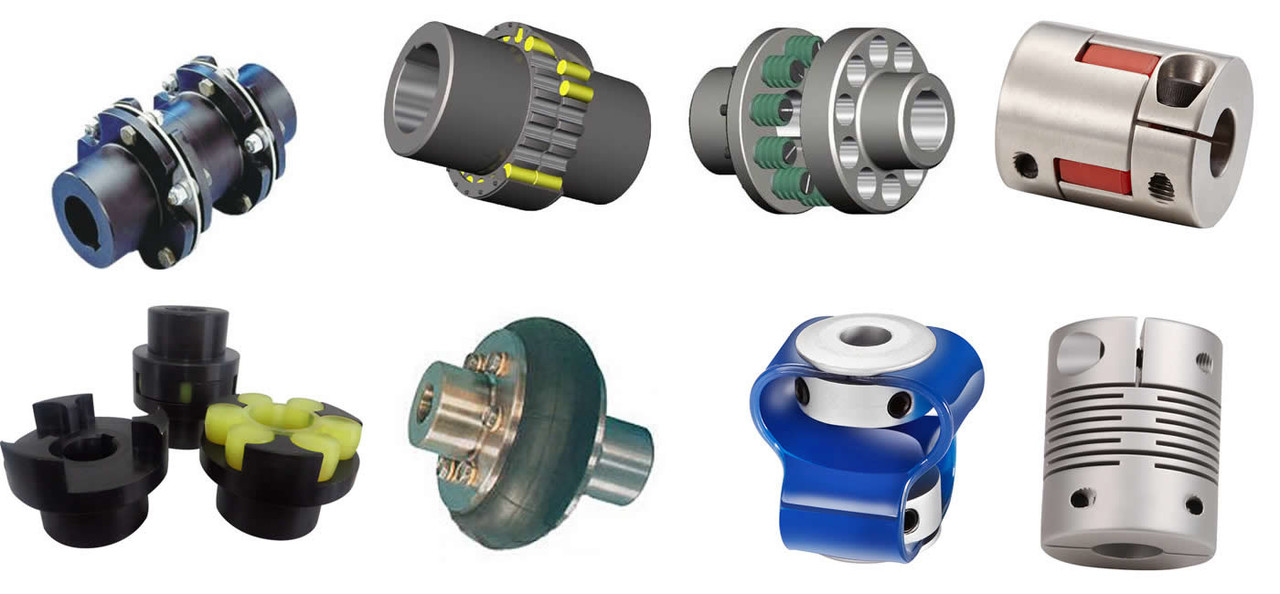
Understanding the Torque and Misalignment Capabilities of Shaft CouplingsShaft couplings play a critical role in transmitting torque and accommodating misalignment between rotating shafts in mechanical power transmission systems. Understanding their torque and misalignment capabilities is essential for selecting the right coupling for a specific application. Here’s an overview: Torque Transmission:The torque capacity of a shaft coupling refers to its ability to transmit rotational force from one shaft to another. It is typically specified in torque units, such as Nm (Newton-meters) or lb-ft (pound-feet). The coupling’s torque capacity depends on its design, size, and material. When selecting a coupling, it’s crucial to ensure that its torque capacity meets or exceeds the torque requirements of the application. Overloading a coupling beyond its torque capacity can lead to premature failure or damage to the coupling and connected equipment. Misalignment Compensation:Shaft misalignment can occur due to various factors, including thermal expansion, manufacturing tolerances, or foundation settling. Misalignment puts additional stress on the coupling and connected components, potentially leading to increased wear and reduced efficiency. Shaft couplings are designed to compensate for different types of misalignment:
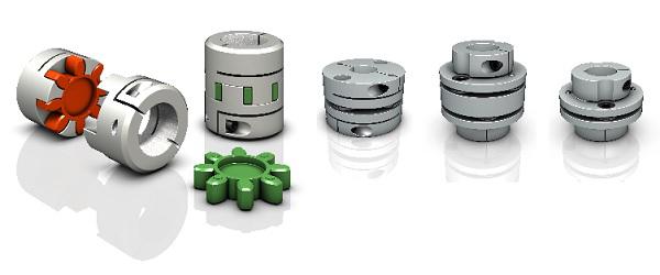
The coupling’s misalignment capabilities are specified in terms of angular and axial misalignment values, usually in degrees or millimeters. Different coupling designs can accommodate varying degrees of misalignment, and the choice depends on the specific application and operating conditions. Flexible Couplings:Flexible couplings, such as elastomeric or jaw couplings, offer good misalignment compensation. They can handle a combination of angular, parallel, and axial misalignments. However, their torque capacity may be limited compared to rigid couplings. Rigid Couplings:Rigid couplings, such as clamp or sleeve couplings, have high torque transmission capabilities but offer minimal misalignment compensation. They are best suited for applications where shafts are well-aligned and precise torque transmission is critical. Torsional Stiffness:Another factor to consider is the coupling’s torsional stiffness, which determines how much torsional deflection or twist occurs under load. Some applications, like precision systems, may require couplings with high torsional stiffness to maintain accurate positioning and avoid torsional backlash. By understanding the torque and misalignment capabilities of shaft couplings, engineers can make informed decisions when selecting a coupling to ensure efficient power transmission and reliable performance in their mechanical systems. “` Comparing Shaft Couplings with Other Types of Couplings in PerformanceShaft couplings are essential components in mechanical power transmission systems, and their performance characteristics vary depending on the coupling type. Let’s compare shaft couplings with other common types of couplings: 1. Shaft Couplings:Shaft couplings come in various designs, including flexible and rigid couplings. They are widely used in a broad range of applications due to their ability to transmit torque and accommodate misalignments between rotating shafts. Flexible shaft couplings, with elastomeric or metallic elements, offer good misalignment compensation and damping characteristics. Rigid couplings, on the other hand, provide precise torque transmission and are ideal for applications where shafts are well-aligned. 2. Gear Couplings:Gear couplings are robust and designed for heavy-duty applications. They consist of two external gear hubs with internal gear teeth that mesh together. Gear couplings can handle high torque, high-speed, and angular misalignment. They are often used in demanding industries such as steel, mining, and paper manufacturing. 3. Grid Couplings:Grid couplings feature a flexible grid element between the two halves of the coupling. They provide excellent shock absorption and misalignment compensation. Grid couplings are commonly used in pumps, compressors, and other industrial machinery. 4. Disc Couplings:Disc couplings utilize flexible metallic discs to transmit torque and compensate for misalignment. They offer high torsional stiffness, making them suitable for applications requiring precise motion control, such as robotics and CNC machines. 5. Jaw Couplings:Jaw couplings consist of two hubs with elastomeric spider inserts. They are easy to install, have good misalignment capabilities, and offer electrical isolation between shafts. Jaw couplings are widely used in light to medium-duty applications. 6. Oldham Couplings:Oldham couplings have three discs—two outer discs with slots and a central disc with a tongue that fits into the slots. They provide excellent angular misalignment compensation while maintaining constant velocity between shafts. Oldham couplings are commonly used in printing machines and conveyors. 7. Beam Couplings:Beam couplings are made from a single piece of flexible material with spiral cuts. They offer good misalignment compensation and torsional flexibility, making them suitable for precision equipment like encoders and servo motors. The choice of coupling depends on the specific requirements of the application, including torque, speed, misalignment compensation, environmental conditions, and space limitations. Each coupling type has its strengths and limitations, and selecting the right coupling is crucial to ensure optimal performance and reliability in the mechanical system. “` How Does a Flexible Shaft Coupling Differ from a Rigid Shaft Coupling?Flexible shaft couplings and rigid shaft couplings are two distinct types of couplings, each designed to serve different purposes in mechanical power transmission. Here are the key differences between the two: 1. Flexibility:The most significant difference between flexible and rigid shaft couplings is their flexibility. Flexible couplings are designed with elements that can deform or flex to accommodate misalignments between the shafts. This flexibility allows for angular, parallel, and axial misalignments, making them suitable for applications where shafts are not perfectly aligned. In contrast, rigid couplings do not have this flexibility and require precise alignment between the shafts. 2. Misalignment Compensation:Flexible couplings excel in compensating for misalignments, making them ideal for applications with dynamic conditions or those prone to misalignment due to thermal expansion or vibrations. Rigid couplings, on the other hand, are used in applications where perfect alignment is critical to prevent vibration, wear, and premature failure. 3. Damping Properties:Flexible couplings, particularly those with elastomeric or flexible elements, offer damping properties, meaning they can absorb and reduce shocks and vibrations. This damping capability helps protect the connected equipment from damage and enhances system reliability. Rigid couplings lack this damping ability and can transmit shocks and vibrations directly between shafts. 4. Torque Transmission:Both flexible and rigid couplings are capable of transmitting torque from the driving shaft to the driven shaft. However, the torque transmission of flexible couplings can be limited compared to rigid couplings, especially in high-torque applications. 5. Types of Applications:Flexible couplings find applications in a wide range of industries, especially in situations where misalignment compensation, vibration damping, and shock absorption are essential. They are commonly used in conveyors, pumps, compressors, printing presses, and automation systems. Rigid couplings are used in precision machinery and applications that demand perfect alignment, such as high-speed spindles and certain types of precision equipment. 6. Installation:Flexible couplings are relatively easier to install due to their ability to accommodate misalignment. On the other hand, rigid couplings require careful alignment during installation to ensure proper functioning and prevent premature wear. The choice between a flexible and a rigid shaft coupling depends on the specific requirements of the application. If misalignment compensation, damping, and flexibility are critical, a flexible coupling is the preferred choice. If precision alignment and direct torque transmission are essential, a rigid coupling is more suitable. “` by Tags: aluminum chain roller, aluminum roller chain, aluminum shaft, aluminum sprockets, chain, chain coupling, chain coupling sprockets, chain roller, chain roller chain, china chain, china coupling, china machinery, china roller chain, coupling, coupling chain, coupling shaft, flexible coupling, flexible roller chain, flexible shaft, flexible shaft coupling, machinery, machinery china, machinery machinery, roller chain, roller chain chain, roller chain coupling, roller chain shaft coupling, roller chain sprockets, roller shaft, roller sprockets chain, roller with chain, roller with shaft, shaft, shaft coupling, shaft part, shaft roller, sprockets chain, sprockets roller chain
Comments |


Leave a Reply