The choice of connection type for gear couplings depends on the connection type of the main and driven ends to the shaft. Generally, the key connection is adopted, which is a unified key connection type and code. The force analysis of the gear transmission is the basis for the strength calculation, including the force analysis of the spur gear, the force analysis of the helical gear and the force analysis of the spur bevel gear, the focus is on the force of the spur gear analysis. In the force analysis of the gear coupling, in order to facilitate the analysis of the problem, the friction force is omitted. The load uniformly distributed along the tooth width is regarded as the concentrated load acting on the end of the tooth width, and it is divided into several component forces.
During load analysis, the point of application of the force should be taken at the pitch circle node at the end of the tooth width of the two gears; the driving wheel and the driven wheel should be distinguished; the direction of the axial force depends on the steering and rotation direction (the direction of the helical tooth). Axial force can be ruled by "left" and "right" hands. Spur gears can be regarded as a special case of helical gears, that is, to master the two strength calculation formulas of cylindrical gears. It is necessary to clarify the mechanical model and theoretical basis of the formula; fully understand the process of formulating the formula, grasp the physical meaning of the coefficients in the formula and the law of the influence of gear parameter changes on these coefficients, including tooth profile coefficients, life coefficients, etc. In addition, grasp the strength of the spur bevel gear and the equivalent spur gear at the midpoint of the tooth width, so you can use the strength formula of the spur gear, as long as its parameters are replaced by the parameters at the midpoint of the bevel gear tooth width, Then convert the parameters at the midpoint of the tooth width to big-endian parameters. Among them, it is necessary to be able to judge the cycle characteristics of bending stress and contact stress according to the specific gear usage conditions.
Gear couplings are unique in that they have low inertia and sensitivity. In practical applications, rigid couplings are easy to maintain and can resist oil and corrosion. And in a high-speed environment, it can compensate for the relative displacement due to high-speed operation. Of course, if the relative displacement can be successfully controlled, it can also exert excellent performance in the servo system. A shaft coupling used in mechanical transmission systems, especially long shaft coupling parts in mechanical transmission in metallurgical plants. This kind of coupling transforms the existing gear coupling into a coupling with different numbers of teeth at both ends, and uses the difference in the number of teeth to adjust the phase angle of each shaft to meet the long shaft transmission with phase angle assembly requirements.
The GCLD drum gear coupling pushes fluid to flow, and the flowing liquid pushes the rotor to rotate, thereby driving the driven shaft to rotate. Since the motor only needs to drive a limited fluid flow when starting, the starting torque is very small; as the motor speed increases, the fluid flow speed increases, and the kinetic energy increases, and gradually push the rotor on the driven shaft to accelerate until it reaches the Speed up to. This kind of coupling is easy and stable to start, and has an overload protection function. However, in the stable operation stage after the start, the main and driven shafts always maintain the speed difference, and the speed difference changes with the load.
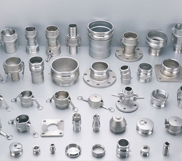
https://www.flexible-shaft-coupling.top/product/stainless-steel-camlock-coupling/stainless-steel-type-b-camlock-coupling.html